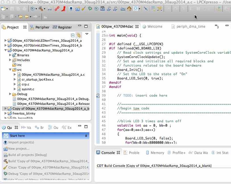
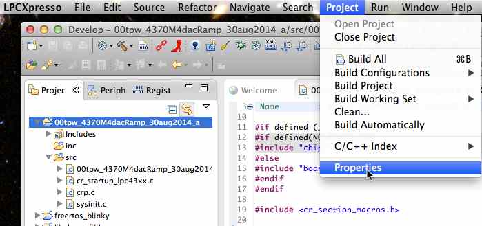
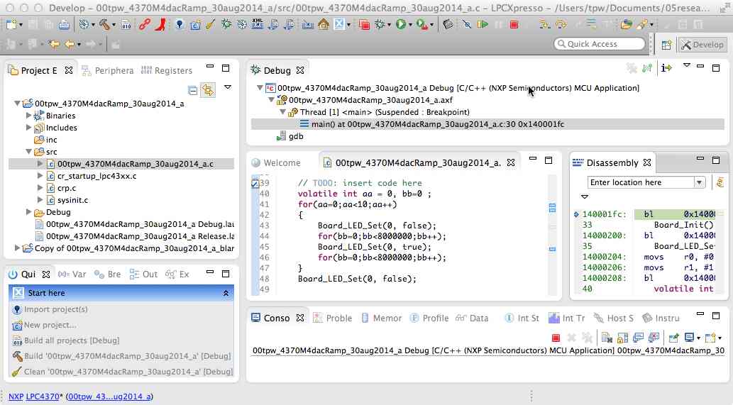
Edit the new "rampDAC" project by replacing the prior code in
main with the following new code:
// TODO: insert code here
//===========================================================
//begin tpw code
//===========================================================
//blink LED 3 times and turn off
volatile int aa = 0, bb=0 ;
for(aa=0;aa<3;aa++)
{
Board_LED_Set(0, false);
for(bb=0;bb<8000000;bb++);
Board_LED_Set(0, true);
for(bb=0;bb<8000000;bb++);
}
Board_LED_Set(0, false);
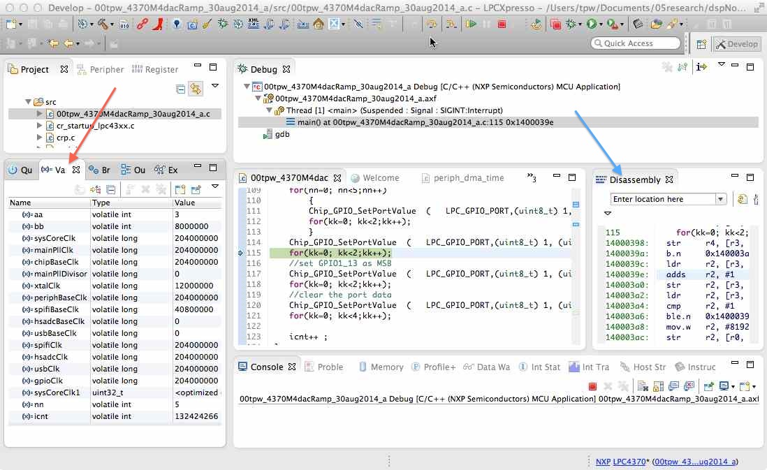
//find rates of various clocks
//it is useful to know your clock rates in driving your DAC
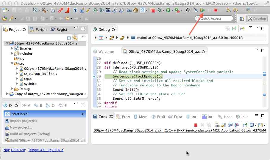
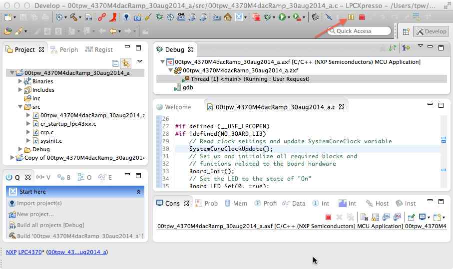
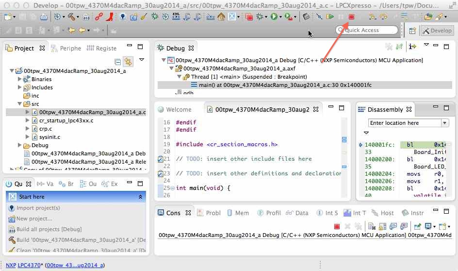
//to see the values on your chip, halt the program and read these variables
volatile static long int sysCoreClk=0,maxSysClk=MAX_CLOCK_FREQ,mainPllClk=0;
volatile static long int chipBaseClk=0,mainPllDivisor=0,xtalClk=0;
volatile static long int periphBaseClk=0,spifiBaseClk=0,hsadcBaseClk=0,usbBaseClk=0;
volatile static long int spifiClk=0,hsadcClk=0,usbClk=0,gpioClk=0;
uint32_t sysCoreClk1=0;
sysCoreClk1 = Chip_Clock_GetRate(CLK_MX_MXCORE);
sysCoreClk=(long int)sysCoreClk1;
mainPllClk=(long int)Chip_Clock_GetMainPLLHz();
chipBaseClk=(long int)Chip_Clock_GetBaseClocktHz(CLKIN_CLKIN);
mainPllDivisor=(long int)Chip_Clock_GetDividerDivisor(CLKIN_MAINPLL);
xtalClk=(long int)Chip_Clock_GetClockInputHz(CLKIN_CRYSTAL);
periphBaseClk=(long int)Chip_Clock_GetBaseClocktHz(CLK_BASE_PERIPH);
spifiBaseClk=(long int)Chip_Clock_GetBaseClocktHz(CLK_BASE_SPIFI);
spifiClk=Chip_Clock_GetRate(CLK_MX_SPIFI);
hsadcBaseClk=(long int)Chip_Clock_GetBaseClocktHz(CLK_BASE_ADCHS);
hsadcClk=Chip_Clock_GetRate(CLK_MX_ADCHS);
usbBaseClk=(long int)Chip_Clock_GetBaseClocktHz(CLK_BASE_ADCHS);
usbClk=Chip_Clock_GetRate(CLK_MX_USB0);
gpioClk=Chip_Clock_GetRate(CLK_MX_GPIO);
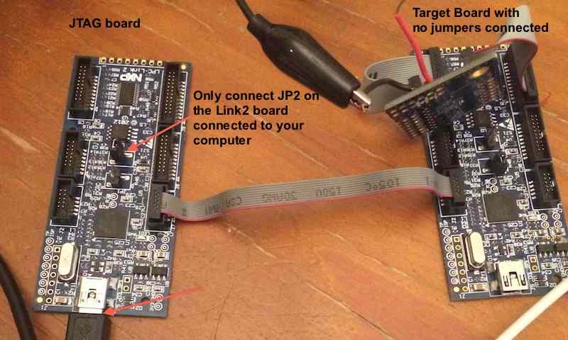
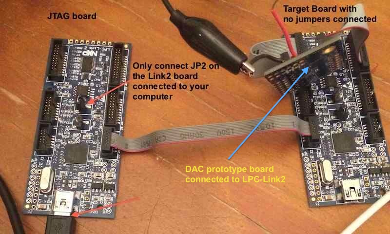
//use LPC-Link2 digital outputs to drive your favorite DAC
//on connector J9 GPIO1 pins 0-4 and 12, 13 are available
//so we use GPIO1_0 as LSB and GPIO1_13 as MSB
//below we clear GPIO1 then set each bit in succession
volatile static int nn = 0 ;
volatile static int icnt = 0 ;
volatile static int kk = 0 ;
//first configure pins as fast output pins
for(nn=0; nn<5;nn++)
{
Chip_SCU_PinMuxSet((uint8_t) 1, (uint8_t)(nn), SCU_PINIO_FAST);
Chip_GPIO_SetPinDIROutput(LPC_GPIO_PORT, (uint8_t) 1, (uint8_t)(nn));
}
Chip_SCU_PinMuxSet((uint8_t) 1, (uint8_t)(12), SCU_PINIO_FAST);
Chip_GPIO_SetPinDIROutput(LPC_GPIO_PORT, (uint8_t) 1, (uint8_t)(12));
Chip_SCU_PinMuxSet((uint8_t) 1, (uint8_t)(13), SCU_PINIO_FAST);
Chip_GPIO_SetPinDIROutput(LPC_GPIO_PORT, (uint8_t) 1, (uint8_t)(13));
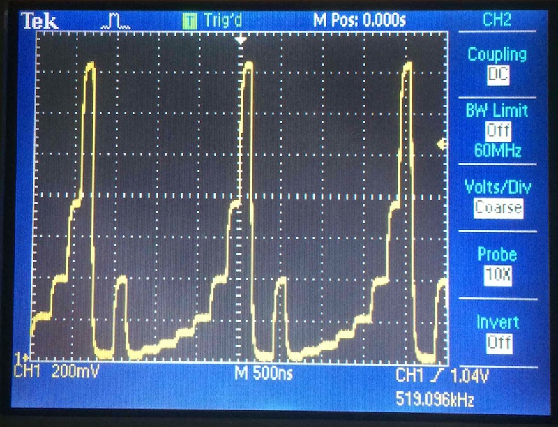
//create infinite loop of DAC output
while(1)
{
//clear the output data on port GPIO1
Chip_GPIO_SetPortValue(PC_GPIO_PORT,(uint8_t) 1, (uint32_t)(0) );
//mark the beginning of the loop by setting a bit high
Chip_GPIO_SetPortValue(LPC_GPIO_PORT,(uint8_t) 1, (uint32_t)(1<<4) );
//use for loop for a short time pause
for(kk=0; kk<2;kk++);
Chip_GPIO_SetPortValue(LPC_GPIO_PORT,(uint8_t) 1, (uint32_t)(0) );
for(kk=0; kk<2;kk++);
for(nn=0; nn<5;nn++)
{
{
Chip_GPIO_SetPortValue(LPC_GPIO_PORT,(uint8_t) 1, (uint32_t)(1<<nn) );
for(kk=0; kk<2;kk++);
}
Chip_GPIO_SetPortValue(LPC_GPIO_PORT,(uint8_t) 1, (uint32_t)(1<<12) );
for(kk=0; kk<2;kk++);
//set GPIO1_13 as MSB
Chip_GPIO_SetPortValue(LPC_GPIO_PORT,(uint8_t) 1, (uint32_t)(1<<13) );
for(kk=0; kk<2;kk++);
//clear the port data
Chip_GPIO_SetPortValue(LPC_GPIO_PORT,(uint8_t) 1, (uint32_t)(0) );
for(kk=0; kk<4;kk++);
icnt++ ;
}
//===========================================================
//end tpw code
//===========================================================
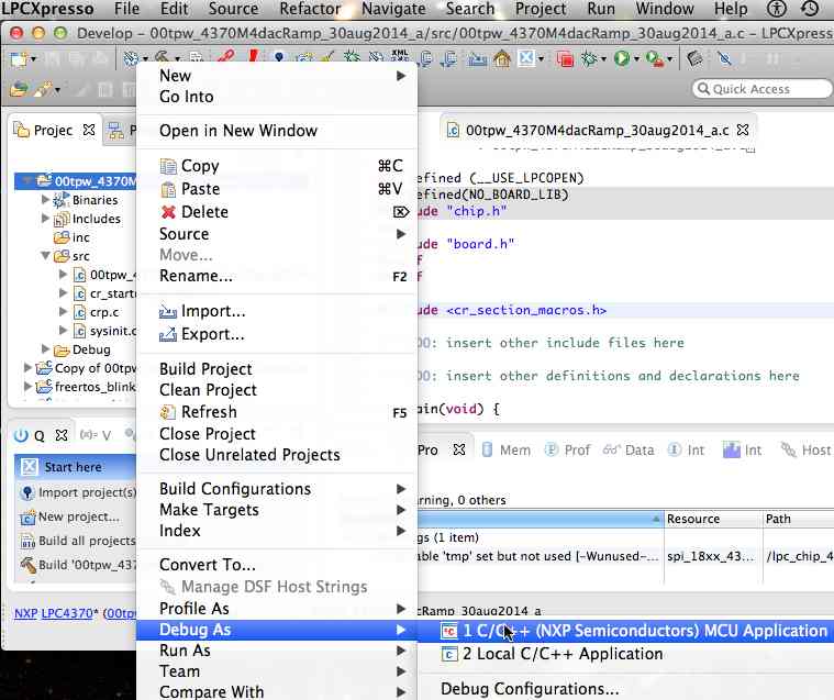
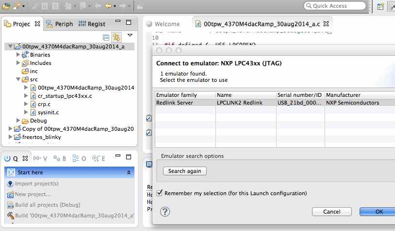
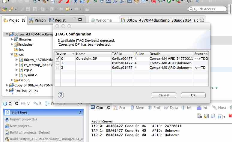
as shown below: