Microwave Circuits and
Metamaterials
Project 10
Overview
Remain in same project groups for the
semester.
The objective of this project is to investigate a double-negative
metamaterial
.
NOTE: Use the Project Report Template and keep answers to questions on consecutive sheets
of paper with all plots at the end.
IN NO CASE may code or files be exchanged between students, and
each student must answer the questions themselves and do their own
plots, NO COPYING of any sort! Nevertheless, students are
encouraged to collaborate in the lab session.
Only turn in requested plots ( Pxx )
and requested answers to questions ( Qxx ).
Part 1
- In the following:
- You will first investigate a double-negative metamaterial
structure, and observe negative relative
permeability and negative relative
permittivity
- The structure consists of a split ring with magnetic (H
field) behavior, and an I-beam with electric (E field)
behavior. The Ibeam is closely related to
capacitively loaded strips (CLS as described in Design,
fabrication, and testing of double negative metamaterials
- You will then remove the split ring from the structure and
observe the negative permittivity induced by the I-beam
- You will remove the I-beam from the structure and observe
the negative permeability induced by the split ring
- Load and run the example as follows:
- Save a snapshot of the design as above and paste it into
your report. ( P1 )
- Make sure that your
plots, component
values,
legends, axes, and fonts are legible in your report!
- Select the Boundaries::perfectH in the project manager pane
on the left side of the HFSS window, and note that these are the short walls of
the parallel-plate waveguide. The perfectH boundary is similar to
perfectE boundary. PerfectE is a perfect conductor that
does not allow tangential electric fields at the
boundary. PerfectH is a perfect magnetic conductor that
does not allow tangential magnetic fields at the
boundary.
- What is the radius of the ring? ( Q1 )
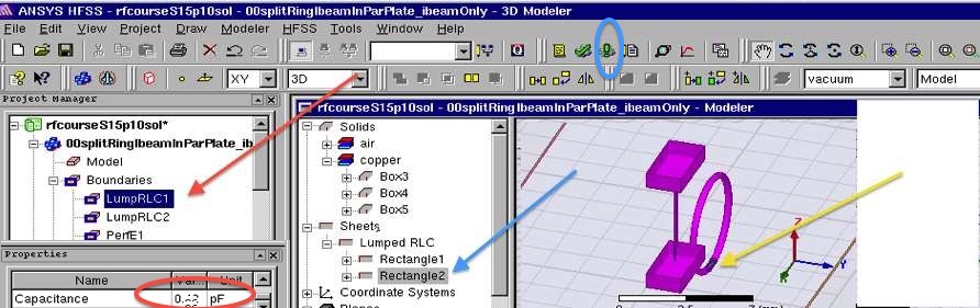
- Zoom in to the gap in the ring by selecting
Boundary::LumpedRLC1 (red arrow below) and zooming in to see
the sheet (yellow arrow below) that is placed in the gap
(Rectangle2 ). This "RLC" sheet is used as a
capacitor in the gap, to set the frequency of resonance of the
ring.
- What is the capacitance (red circle below) of the RLC sheet
in the gap of the ring? ( Q2 )
- Zoom in to the gap in the I-beam post by selecting
Boundary::LumpedRLC2 and zooming in to see the sheet
that is placed in the Ibeam post gap (Rectangle1
). This "RLC" sheet is used as an inductor in the
gap, to set the frequency of resonance of the I-beam.
- What is the inductance of the RLC sheet in the gap of the
I-beam post? ( Q3 )
- Save your work, MenuBar::File::Save
- MenuBar::HFSS::ValidationCheck and Everything should
check OK
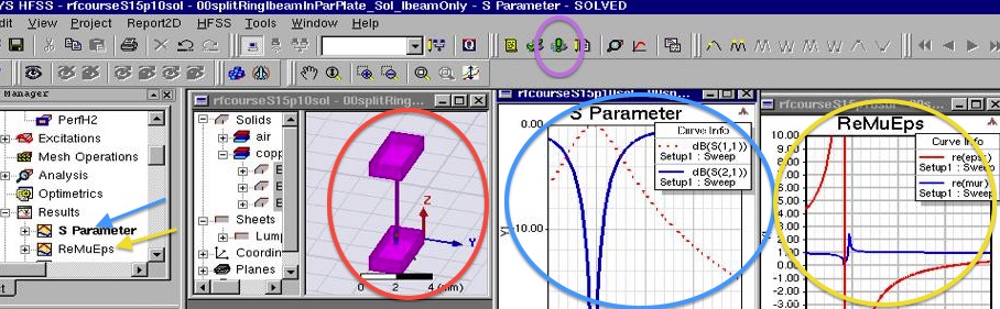
- MenuBar::HFSS::AnalyzeAll (blue circle above) to run the
simulation
- Watch for any errors at the bottom message areas (red arrows
below)
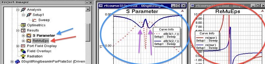
- Open the Plots for S-parameters (red arrow and circle below)
and ReMuEps (blue arrow and circle below) (permittivitty
and permeability)
- Save a snapshot of the S-parameters plot (blue arrow and
circle above) and paste it into your report.
( P2 )
- Save a snapshot of the ReMuEps (real parts of relative
permeability "mur" and relative
permittivity "epsilonr") plot (red arrow and circle
above) and paste it into your report. ( P3 )
- What are the lower and upper frequencies of the band where
both mu and epsilon are both negative?
( Q4 )
- The double-negative passband lies in the middle of the "dip"
in S21. What are the lower and upper frequencies (purple
arrows above) of the double-negative passband where both mu
and epsilon are both negative? ( Q5 )
- Save your work!
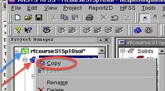
- Measure the I-beam by itself
- Make a copy of the design by selecting the design (red arrow
below) and right-click copying (red circle below)
- Then pasted the copy into the main folder (blue arrow below)
by right-click pasting the main folder
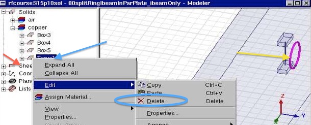
- Next delete the ring (torus) by selecting the torus (blue
arrow below) and the torus should be highlighted (yellow arrow
below)
- Then right-click to delete the torus (blue circle below)
- Repeat the same procedure to delete the "RLC" sheet by
selecting rectangle2 under the sheets (red arrow below). Make sure to check that you select
the sheet that was in the gap of the ring.
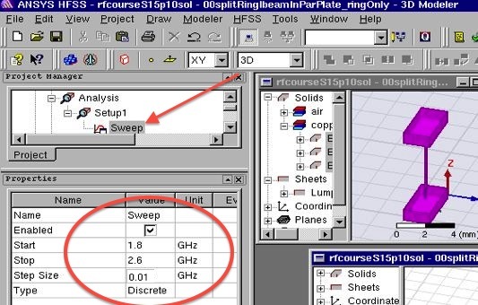
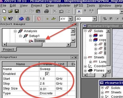
- Finally, adjust the frequency sweep (red arrow below) to set
the sweep parameters as indicated (red circle below)
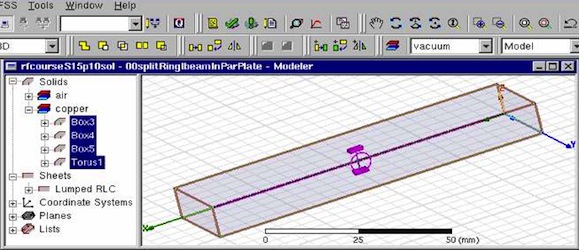
- After deleting the torus, and resetting the sweep parameters
your design should only include the I-beam as in the red
circle below
- Run the simulation (purple
circle above)
- Save a snapshot of the I-beam without torus (red circle
above) and paste it into your report. ( P4 )
- Save a snapshot of the S-parameters plot (blue arrow and
circle above) and paste it into your report.
( P5 )
- Save a snapshot of the ReMuEps (real parts of mu and
epsilon) plot (red arrow and circle above) and paste it into
your report. ( P6 )
- What is the frequency of the minimum in S21? ( Q6 )
- What is the frequency where epsilon is its most negative
value? ( Q7 )
- The frequency the most negative epsilon has moved, since the
ring is no longer nearby.
- Notice the stopband in the region of negative permittivity
that became a passband when the negative permeability of the
ring was present to provide a double-negative material.
- Save your work!
- Measure the split ring by itself
- Make another copy of the design, as before
- In this case, delete the I-beam to measure the response of
the split ring by itself
- Set the frequency sweep as follows (same as for Ibeam only)
- After deleting the I-beam structures and
inductor sheet, your design should only include the
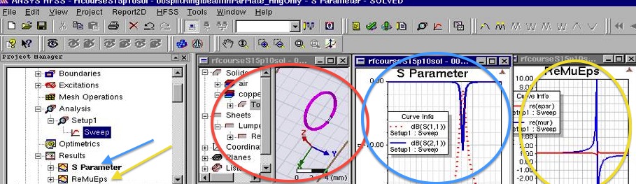
spit ring as in the red circle below
- Run the simulation
- Save a snapshot of the ring without the I-beam (red circle
above) and paste it into your report. ( P7 )
- Save a snapshot of the S-parameters plot (blue arrow and
circle above) and paste it into your report.
( P8 )
- Save a snapshot of the ReMuEps (real parts of mu and
epsilon) plot (red arrow and circle above) and paste it into
your report. ( P9 )
- What is the frequency of the minimum in S21? ( Q8 )
- What is the frequency where mu has its most negative
value? ( Q9 )
- The frequency at the most negative value of mu has not
significantly moved, since the ring is not much affected by
the Ibeam.
- Notice the stopband in the region of negative permeability
that became a passband when the negative permittivity of the
Ibeam was present to provide a double-negative material.
- Exit the program, File->Exit
NOTE ReportTemplate: Use the Project Report Template
and keep answers to questions on
consecutive sheets of paper with all plots at the end.
Do not add extraneous pages or put explanations on separate
pages unless specifically directed to do so. The instructor will
not read extraneous pages!
Only turn in requested plots (Pxx )
and requested answers to questions (Qxx ).
All plots must be labeled P1, P2, etc. and all questions must be
numbered Q1, Q2, etc. YOU MUST ADD CAPTIONS AND FIGURE
NUMBERS TO ALL FIGURES!!
Copyright 2010-2015 T. Weldon
Cadence, Spectre and Virtuoso are registered trademarks of
Cadence Design Systems, Inc., 2655 Seely Avenue, San Jose, CA
95134. Agilent and ADS are registered trademarks of Agilent
Technologies, Inc.