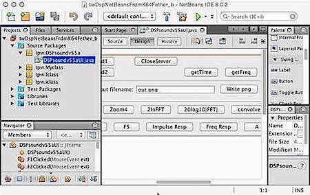
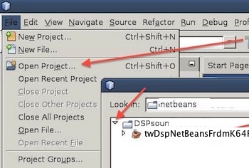
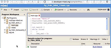
NetBeans interface builder on left, FRDM-K64F board on right.
Before doing anything, look over these items first:
- A video of recommended board and some of the associated parts (check syllabus for latest list of parts)
- FRDM-K64F mbed website
This tutorial describes the use of Java/NetBeans to create a graphic interface that runs on a laptop with capability of sending and receiving messages and data over Ethernet/TCP to the RJ-45 port of an NXP FRDM-K64F. In addition, this tutorial briefly describes the use of the mbed.org online compiler interface to program the FRDM-K64F to receive/send data over Ethernet/TCP, run the ADC (analog-to-digital converter), run the DAC (digital-to-analog converter), and perform a fast Fourier transform using the mbed CMSIS DSP library. The FRDM-K64F has an ARM Cortex-M4 core running up to 120MHz, 1024KB Flash, 256KB RAM, 16-bit ADCs, 12-bit DAC, and Timers. The NetBeans interface builder is shown on the left below, and the FRDM-K64F board is on the right below. (Note picture below for correct usb port on FRDM-K64F)
The following sections cover:
To get your project up and running quickly, we will just compile the interface program "as is" in NetBeans (on your laptop), download the the binary to the FRDM-K64F, and run the software "as is."
We will be using the FRDM-K64F mbed boards and your personal laptops for our projects, where the laptop acts as a server to control the FRDM-K64F mbed board as a client over Ethernet RJ-45 cables. We will primarily use the mbed.org online compiler to create, edit, and compile client-side software program code for the FRDM-K64Fboard. NetBeans on your personal laptops will be used to create, edit, and compile server-side software program code
- The following links should help briefly familiarize you with the hardware:
- A video of recommended board and some of the associated parts (check syllabus for latest list of parts)
- FRDM-K64F mbed website
2.1 Install Netbeans
In 2016, do not install any version of NetBeans later than 8.0. Version 8.0 works, but version 8.1 has the "JUnit hamcrest" bug. Make sure to install the full version package that includes the Java and C++ tools. If you do not have NetBeans installed on your laptop, install NetBeans.
The NetBeans IDE is a tool for building applications and allows the user to quickly add buttons and widgets to a custom GUI (Graphical User Interface). Downloads and documentation for NetBeans are available on https://netbeans.org . WARNING: if you decide to download NetBeans to your home computer, make sure that you get the same or recommended version as being used in class.
2.2 Sign up for an mbed.org developer account and download the course software
Mbed.org hosts an online compiler that we will use to create, edit, and compile program code for the FRDM-K64Fboard. Follow the steps below to obtain an mbed.org account to access the compiler, and follow the instructions to update your firmware before doing anything else.
- Sign up for an mbed.org developer account and make sure that you agree to their license
- FIRST, MAKE SURE that your FRDM-K64F board firmware is updated to latest version!
- check here: https://developer.mbed.org/handbook/Firmware-FRDM-K64F for updates to FRDM-K64F boards
- and also check here: https://developer.mbed.org/platforms/FRDM-K64F/ for updates to FRDM-K64F boards
- Familiarize yourself with the Mbed.org web-based IDE (integrated development environment)
- The mbed IDE will be our main vehicle for sharing and compiling projects/code
- Mbed IDE does not support debug (to do debug, you would need KDS/KSDK IDE below or Improvised eclipse/platformio IDE described below)
- Once logged into your mbed.org account you should navigate to the developer area at https://developer.mbed.org/ or directly to the mbed compiler at https://developer.mbed.org/compiler/ as illustrated below
Mbed.org compiler view.
- You will use the mbed.org tools to upload your project software for compilation
Download the course software
- Download the tpwNetBeansEtherMbedK64Fbundle_b.zip software bundle zip-file containing:
- twDspNetBeansFrdmK64Fether_b.zip zipfile of the NetBeans interface
- frdm_etherClient_netBeans_b_zip_k64f.zip containing FRDM-K64F mbed source code
- frdm_etherClient_netBeans_b_K64F.bin pre-compiled binary file to be loaded onto your FRDM-K64F
If you have not already done so, update our FRDM-K64F board firmware is updated to latest version!
- check here: https://developer.mbed.org/handbook/Firmware-FRDM-K64F for updates to FRDM-K64F boards
- and also check here: https://developer.mbed.org/platforms/FRDM-K64F/ for updates to FRDM-K64F boards
2.3 Load the software binary into the FRDM-K64F and run it
The next step is to load the binary onto the FRDM-K64F board to execute the code. In a later section below, editing the source code in mbed will be discussed. For present purposes of getting everything up and running, only the binary executable is needed.
- If you have not already done so, update your FRDM-K64F board firmware is updated to latest version, as noted above!
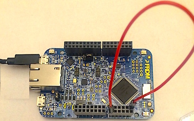
- Plug the FRDM-K64F board into the USB port of the laptop to power-up the board (see pictures below for correct usb port on FRDM-K64F)
- Open two file-browsers, file-managers, file-navigators, or finders (depending on what your laptop's operating system calls them)
- One file-browser should be opened to the USB device corresponding to your FRDM-K64F
- The second file-browser should be opened to the directory containing your dowloaded binary frdm_etherClient_netBeans_b_K64F.bin
- In the two file-browsers, drag frdm_etherClient_netBeans_b_K64F.bin into your FRDM-K64F
- If dragging the file does not work on some Apple/Mac systems, it may be necessary to transfer the file to the FRDM-K64F board using a command line from a terminal. In such a case, try:
- sudo mount -u -w -o sync /Volumes/MBED ;cp -X /Users/tpw/Downloads/ tp_frdm_Gain8negCap_02_1us_K64F.bin /Volumes/MBED/
- When you drag the file, the green LED near the USB port on the FRDM-K64F should flash as the program is loaded, as shown below
Flashing green LED as program is loaded.
- Next, run/execute the FRDM-K64F program that was just loaded
- Once the green LED above stops flashing, the file has been loaded
- Press the reset button (blue arrow below) near the LED that flashed as shown below
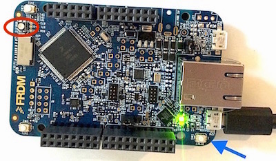
Reset button (blue arrow) on FRDM-K64F, and RGB-LED (red circle).
- After you press reset (blue arrow above), your program will start running, and the RGB-LED (red circle above) should turn blue
Run the software on the FRDM-K64F with teh ADC connected to the DAC
- Next, power-down the board by unplugging the usb cable
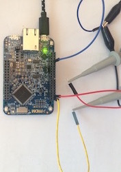
- Connect a jumper wire between the DAC0out pin and the A0/PTB2 pin of the FRDM-K64F as shown below:
Jumper wire connecting the DAC0out pin and the A0/PTB2 pin of the FRDM-K64F.
- Power-up the board by plugging the USB cable into the laptop
- Press the reset button on the FRDM-K64F, and the RGB-LED should turn blue
2.4 Run a tty/terminal to see output from the FRDM-K64F
- Press the reset button on the FRDM-K64F, and the RGB-LED should turn blue
- The FRDM-K64F program emulates a tty/serial/terminal through the USB port, and communication requires a second tty/serial/terminal program that runs on the laptop
- On a PC, a tty/serial driver is needed,
- See the instructions for win/PC tty/serial/com/terminals on https://developer.mbed.org/handbook/Windows-serial-configuration and https://developer.mbed.org/handbook/Terminals
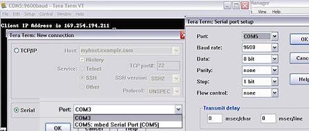
- Suggested terminal program is TeraTerm
- Settings are 9600 baud, N81 (no parity, 8-bit data, 1 stop bit)
- The picture below is for a TeraTerm setup on a winXP PC:
Terminal settings for TeraTerm on a winXP PC.
- On an Apple/Mac, open a new command terminal (Applications/Utilities/Terminal.app) and run the following commands:
- Use the command "ls /dev | grep usb" to make sure of the name of your USB tty/serial/terminal device on the laptop before running the screen command
- The foregoing command may report a tty such as: /dev/tty.usbmodem1412
- Finally, use the command "screen /dev/tty.usbmodem1412 9600" to run the "screen" terminal program in the window
- Note: "ctrl-a" followed by "D" is the control sequence to end a session
- It may be necessary to run the commands "tset" to reset terminal, or "ps" to find an unkilled screen, or "kill" to kill the screen job number
- The terminal session may look like:
tpw$ ls /dev | grep usb
cu.usbmodem1412
tty.usbmodem1412
tpw$ screen /dev/tty.usbmodem1412 9600
- Press the reset button on the FRDM-K64F, and the RGB-LED should turn blue
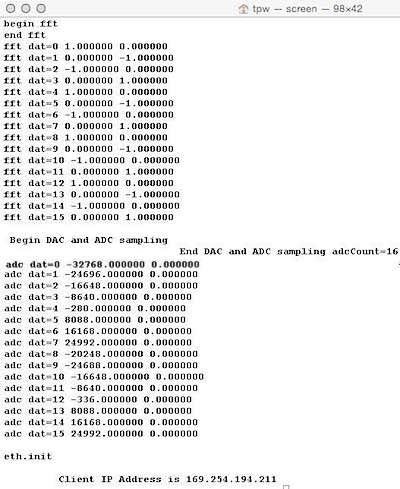
- If all goes well, the terminal session output should appear something like the session below:
Terminal session output from FRDM-K64F after pressing reset button.
- Do not be concerned about the details of the program for now. The important task is to make connection to the terminal through the usb port.
- Hint: if a command terminal ever seems to be in a strange state, type the tset command to reset it
- Nevertheless, a few things can be gleaned from the terminal output above:
- The FRDM-K64F first did an FFT on some data
- Then, the 16 complex-valued output results of the FFT were printed
- Then, the DAC (digital-to-analog converter) generated 16 sample voltages and simultaneously the ADC (analog-to-digital converter) digitized those same 16 voltages (because you connected them with the jumper wire)
- Finally, the board tries to establish an Ethernet connection with FRDM-K64F board address of 169.254.194.211 and keeps waiting, because no Ethernet is setup/connected to the RJ-45 connector of the laptop
2.5 Compile and run the NetBeans GUI server-software used in the course
The next step is to compile and run the NetBeans software and verify that it communicates with the FRDM-K64F over the Ethernet RJ-45 interface.
- In the downloaded course software above, unzip the NetBeans source code file twDspNetBeansFrdmK64Fether_b.zip into your favorite NetBeans directory/folder
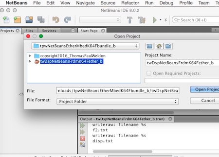
- Run NetBeans and use File::OpenProject and navigate to find the project as shown below
Opening the course software from within NetBeans.
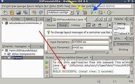
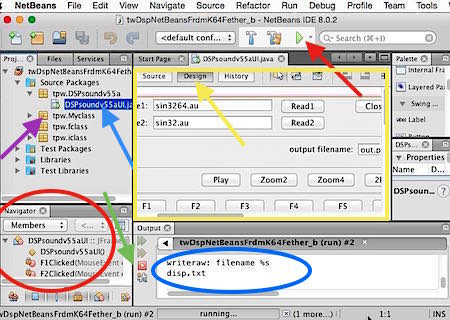
- When the project is loaded, navigate down to the twDspNetBeansFrdmK64Fether_b DSPsoundv55UI (blue arrow below) and double-clcik it to show the GUI as shown below
NetBeans showing the interface provided in the course software.
- If the GUI (yellow box above) is not visible, click the design tab (yellow arrow above)
- The left side of the NetBeans window shows the file structure and allows navigation
- The lower left side of the NetBeans window (red circle) shows the class and member functions in DSPsoundv55aUI
- When a program is running, a text area (blue circle) shows print command output from the NetBeans program as it executes
- The red button (green arrow) will terminate a running program
- The two most important functions for the FRDM-K64F are jGetFreqButtonMouseClicked and jGetTimeButtonMouseClicked and jCloseServerButtonMouseClicked. These functions are most easily accessed by right-clicking the "getTime" or "getFreq" buttons in the interface, and choosing Events::Mouse::mouseClicked submenu; this takes you directly to the source code
- Note also that there are two important Ethernet access functions in tpw.myClass (purple arrow above): k64fGetFreqData() and k64fGetTimeData(),
and these fetch time and frequency data from a FRDM-K64F board
- Build and run the GUI by clicking the triangular green build button (red arrow above)
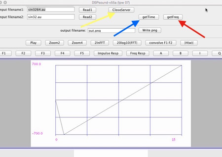
- The twDspNetBeansFrdmK64Fether_b DSPsoundv55UI NetBeans course software program should run and appear as shown below
NetBeans course software program twDspNetBeansFrdmK64Fether_b DSPsoundv55UI compiled and running.
- For the FRDM-K64F, the most important buttons on the twDspNetBeansFrdmK64Fether_b DSPsoundv55UI interface are:
- The "getTime" button (blue arrow above) FRDM-K64F which fetches an array of complex-valued (real and imaginary) time-domain data from the FRDM-K64F
- The "getFreq" button (red arrow above) which fetches an array of complex-valued (real and imaginary) frequency-domain data from the FRDM-K64F
- Note: the Ethernet connection is not established until after pressing the NetBeans getTime or getFreq button
- The "Close-Server" button (yellow arrow above) which closes the Ethernet connection between the laptop and the FRDM-K64F
- Note: to re-establish connection, reset the FRDM-K64F, and press the NetBeans getTime or getFreq button
2.6 Compile the FRDM-K64F client-software on the mbed compiler
The binary software that was loaded onto the FRDM-K64F has hard-coded Ethernet addresses that are not likely to be suitable for most local networks or user laptops. Therefore, it is important to be able to change the Ethernet addresses in the code, to work with your laptop and your local area network. The following describes the steps to upload the frdm_etherClient_netBeans_b code to mbed.org, edit the Ethernet addesses, and re-compile the code.
Importing the FRDM-K64F project into mbed
- The file frdm_etherClient_netBeans_b_zip_k64f.zip that was downloaded in the above section contains the FRDM-K64F mbed source code
- Login to the mbed classic developer/compiler site
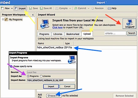
- Click the import button, and select the upload tab (yellow arrows below)
Mbed import of course software.
- Choose the zip file frdm_etherClient_netBeans_b_zip_k64f.zip (blue arrows above) that was downloaded in the above section containing the FRDM-K64F mbed source code
- Click the import button (red arrow above)
- In the popup, select programs (purple arrow)
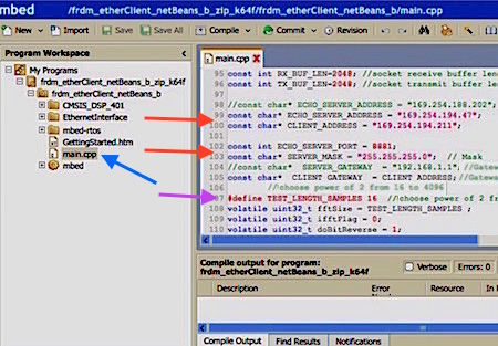
- Once the program is imported, open the main.cpp file (blue arrow below) by double-clicking main.cpp
View of main.cpp, showing server addresses and port number.
- The lines of code near line 100 at the red arrows set the addresses and ports of the FRDM-K64F and laptop, from the point of view of the FRDM-K64F board
- The lines of code near the purple arrows set the size of the number of points gathered by the ADC and the size of the FFT performed by the FRDM-K64F board
- Go to the code area near line 100 (red arrows above) where the the server address, server mask, and server port are set (the laptop is the server) and the client address is set (the FRDM-K64F is the client). These lines are similar to:
const char* ECHO_SERVER_ADDRESS = "169.254.194.47";
const char* CLIENT_ADDRESS = "169.254.194.211";
const int ECHO_SERVER_PORT = 8881;
const char* SERVER_MASK = "255.255.255.0"; // Mask
- It may be necessary to change these lines of code, depending on the operating system, local network, and laptop vendor, as noted below
2.6.1 Checking the Ethernet address (or forcing the address on a PC/winXP)
- On a PC/winXP, the address of the RJ-45 port does not appear to be automatically assigned. Instead, it seems easier to just set the address of the PC/winXP laptop to the FRDM-K64F pre-programmed address 169.254.194.47, as follows:
- Note: If the following step is possible on your laptop, you will not need to change and re-compile your FRDM-K64F code
- You may need to disable firewalls on your laptop to access the FRDM-K64F over Ethernet
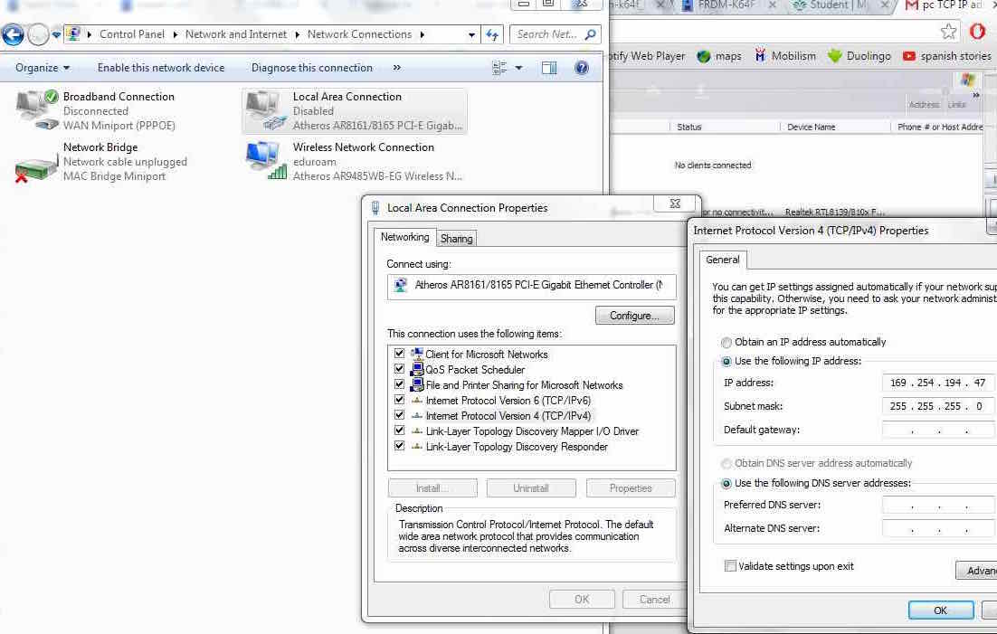
- In window controlPanel andnavigate down through the NetworkingTasks, ChangeSettings, LocalAreaNetworks, LocalAreaConectionStatus, LocalAreaConnectionProperties, InternetProtocolTcpIpProperties and edit "Use the following IP address" to IP address 169.254.194.47 and subnetMask 255.255.255.0. A PC/winXP example is in this picture of setting IP on winXP or for win7 picture of setting IP on win7 .
- On an Apple/Mac, to determine the address of the RJ-45 port:
- Unplug the FRDM-K64F USB from your laptop to turn the board off
- Turn off any wifi or Ethernet ports that may be connected to routers or internet,
- on Mac/OSX open systemPreference::networks, click wifi, and turn wifi off
- Determine the Ethernet address by:
- Connecting an RJ-45 Ethernet cable between the mac laptop and FRDM-K64F
- Plug in the USB to power-up the FRDM-K64F
- You may need to disable firewalls on your laptop to access the FRDM-K64F over Ethernet
- On the mac OSX laptop, open systemPreference::networks
- Open the ethernet item and note the ethernet address such as 169.254.194.47
- Optional: turn wifi back on and check that the Ethernet address (not wifi address) does not change
- OSX/Yosemite seems to automatically self-assign an address to the laptop, such as 169.254.194.47, once the laptop senses the powered-up Ethernet of the FRDM-K64F (so the FRDM-K64F must be turned on for the laptop to self-assign)
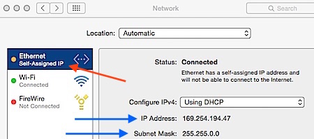
- The laptop Ethernet address and subnet mask (blue arrows below) can be determined as shown below
Finding the IP address of the RJ-45 on an Apple/Mac/Yosemite.
- Note that the Apple/Mac/Yosemite has chosen a "self-assigned" IP address (red arrow above)
- Note: the FRDM-K64F must be turned on for the laptop to self-assign
- These laptop data (blue arrows above) should be entered into the main.cpp program for the ECHO_SERVER_ADDRESS and the SERVER_MASK.
- Also edit the code to set the ECHO_CLIENT_ADDRESS so the first 3 numbers of the ECHO_CLIENT_ADDRESS match the first 3 numbers of the server ECHO_SERVER_ADDRESS
- You need do nothing for the port number variable in main.cpp, since it is set correctly by the NetBeans software
2.6.2 Changing/editing the Ethernet address on the FRDM-K64F
- If the address must be changed, and after editing main.cpp with the corrected addresses on PC or Mac laptops:
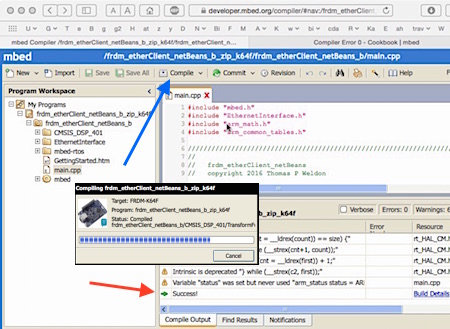
- Compile a new copy of the program in mbed by clicking the compile button (blue arrow below)
- The new binary is automatically exported to the download area of the laptop
Mbed compiling main.cpp.
- If all goes well, the compiler will report success (red arrow above), and will automatically download the new binary to your laptop.
- Ignore the warnings above the "success message," since they seem to disappear at the second time a compile is performed. If the warnings do not disappear at the second compilation, take time to investigate any remaining warnings.
- If changes were necessary, load any new/edited binary as previously described in load the binary onto the FRDM-K64F described above
2.7 Run everything: NetBeans communicates with the FRDM-K64F
Once the Ethernet addresses are correctly set in the FRDM-K64F and laptop, it should be possible to test that the NetBeans program on the laptop is able to communicate properly with the FRDM-K64F.
To start all over, after turning everything off:
- Start the laptop
- Connect the RJ-45 Ethernet cable between the laptop and FRDM-K64F,
- Place a wire jumper between the DAC0out pin and the A0/PTB2 pin of the FRDM-K64F
- Plug in the USB to power up the FRDM-K64F
- You may need to disable firewalls on your laptop to access the FRDM-K64F over Ethernet
- Check that the laptop Ethernet address has not changed, or if needed, re-enter the address on a PC/winXP as described above
- If the Ethernet addresses have changed, edit the Ethernet address on the FRDM-K64F as described above
- Start NetBeans on the laptop
- In NetBeans, open the file twDspNetBeansFrdmK64Fether_b project, and compile and run the NetBeans project as described above
- On the laptop, start a tty/serial/terminal as described above, to see tty output from the FRDM-K64F
- Most likely, some tty output similar will appear, such as: "Unable to connect to (169.254.194.47) on port (8881) eth.getIPAddress= 169.254.194.211"
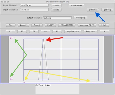
- Press the getTime button (blue arrow below) on the running NetBeans program window, and the RGB-LED on the FRDM-K64F should turn green, and the time data should be displayed as follows:
NetBeans running program window after getTime button is pressed.
- Note that the above is not "real data." The example code simply uses an array of "test data" to verify the Ethernet interface.
- The window should display 16 time data points (yellow arrows above) from 0 to 15
- The peak value (red arrow above) should be 1, and all other values zero (green arrows above)
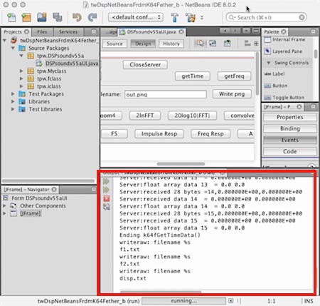
- Also, after pressing the getTime button, the NetBeans output area (red box below) should also contain messages such as below
Printout are in NetBeans after getTime button is pressed.
- Also, after pressing the getTime button, the TTY output of the terminal should have messages such as:
txbuf=14,0.000000E+00,0.000000E+00
txbuf=15,0.000000E+00,0.000000E+00
begin while isconnected
waiting for message from server
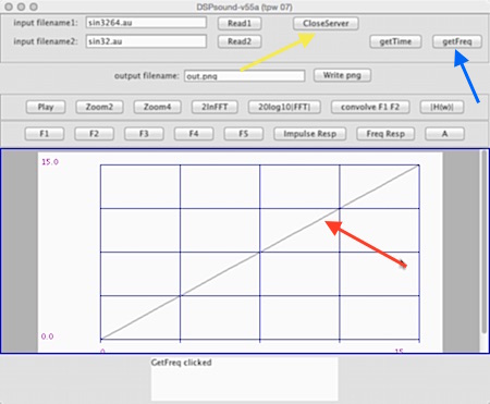
- Press the getFreq button (blue arrow below) on the running NetBeans program window, and the RGB-LED on the FRDM-K64F should turn green, and the frequency-domain data should be displayed as follows:
NetBeans running program window after getFreq button is pressed.
- Note that the above is not "real data." The example code simply uses an array of test data to verify the Ethernet interface.
- The window should display 16 frequency data points (red arrow above) comprising a ramp (the frequency "test data" is a ramp).
- Finally, press the CloseServer button (yellowarrow above) and the RGB-LED on the FRDM K64F should turn red
- After the server is closed, to re-establish the connection, reset the FRDM-K64F board and clcik the getTime button again
2.8 Optional items
You may wish to install one of the offline IDEs to work offline or to have debug capability (mbed.org comiler does nto support debug)
- Optional Installation of Freescale KDS/KSDK IDE
- Install the primary recommended offline IDE: Freescale KDS/KSDK on your laptop or home computer
- KDS/KSDK (Kinetis Design Studio and Kinetis Software Development Kit) is Freescale's free IDE that can support debug and disassembly
- I strongly emphasize DO NOT follow my instructions for a PC or Linux, follow Freescale INSTRUCTIONS for PC or Linux
- Strongly suggest you review my Mac KDS/KSDK installation instructions (even though it is for for Mac systems)
- These are the only known instructions for KDS/KSDK with working debug on Apple/Mac systems
- If you do not have Apple/Mac system, here are the Freescale KDS/KSDK installation instructions for PC/Linux/Mac:
- I strongly emphasize DO NOT follow my instructions for a PC or Linux, follow Freescale INSTRUCTIONS for PC or Linux
- KDS (Kinetis Design Studio) Integrated Development Environment (IDE)
- For PC and Linux, KDS Freescale installation instructions are in Section 1.2 and Section 2.5 of Kinetis Design Studio V3.0.0- User's Guide
- KSDK (KINETIS-SDK): Software Development Kit
- Optional Installation of Improvised Eclipse/Platformio IDE
- As an alternative offline IDE, if you cannot install KDS/KSDK, try this improvised Eclipse/Platformio IDE
- Instructions for Mac-based improvised Eclipse/Platformio open-source IDE/devKit
- Here are some tips for a UNCC install on a PC: PC-based improvised Eclipse/Platformio
We will be using the FRDM-K64F mbed boards for our projects, and we will primarily use the mbed.org online compiler to create, edit, and compile program code for the FRDM-K64Fboard. The following sections describe the FRDM-K64F hardware and the software used in the course.
FRDM-K64F hardware background info and users guides
The following links should help familiarize you with the hardware. The FRDM-K64F has an ARM Cortex-M4 core running up to 120MHz, 1024KB Flash, 256KB RAM, 16-bit ADCs, 12-bit DAC, and Timers.
- A video of recommended board and some of the associated parts (check syllabus for latest list of parts)
- FRDM-K64F mbed website
- FRDM-K64F Freedom Module User’s Guide
- K64 Sub-Family Reference Manual
- FRDM-K64F schematic
- FRDM-K64F has an ARM Cortex-M4 core
Note on dc bias for FRDM-K64 ADC input
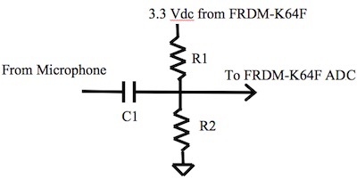
The input range for the FRDM-K64F ADC (analog-to-digital converter) is approximately 0 to 3.3 Volts. Therefore, to digitize an audio signal, it is best to add a blocking capacitor to revent any external dc voltages, and add a 1.65 volt dc bias after the blocking capacitor as illustrated below. Suggested values are C1=1uF and R1=R2=2000 ohms. If audio gain is needed for a project, a useful audio amplifier is the TLV2462 in the DIP package.
Suggested circuit for interfacing between and external audio signal and the ADC on the FRDM-K64F.
ARM, mbed, and FRDM-K64F software info and users guides
- The mbed IDE will be our main vehicle for sharing projects/code
- See the the Mbed.org web-based IDE (integrated development environment)
- See the Mbed basic libraries for many available functions (analogIn, digitalOut, serial, etc.)
- For signal processing in the embedded processor of the FRDM-K64F
- See the Mbed CMSIS DSP libraries for DSP functions (FFT, matrices, serial, etc.
- See the EthernetInterface and sockets and new networking stack for IoT
- ARM Cortex-M4 Devices Generic User Guide (ARM DUI 0553) programmer manual.
Optional: Simple mbed FRDM-K64F Blinky Example
- Optional:
- See the simple mbed Blinky Example if you wish to do a more simple example
- Only do part 1 of the Blinky Example, if you plan to only use mbed
- Part 2 of the example is useful to get KDS/KSDK IDE or improvised Eclipse/Platformio IDE working
Overview of the FRDM-K64F code in mbed
The following describes the software code for the project.
Libraries in FRDM-K64F mbed code
A number of libraries are used in the code.
- Near line 1: The first few lines call out libraries needed to run the code:
- Follow hyperlinks to documentation for the libraries
#include "mbed.h" //functions for LED, print, ADC, DAC, digital I/O
#include "EthernetInterface.h" //used to do Ethernet and TCP
#include "arm_math.h" //used in math and DSP and FFT
#include "arm_common_tables.h" //used in math and DSP and FFT
- Near line 86: Several lines declare I/O, LEDs, serial port tty, ADC, DAC, and timer
- Follow hyperlinks to documentation for the libraries
DigitalOut pinD0(D0); //a digital output
DigitalOut grnled(LED_GREEN); //green RGB-LED
DigitalOut bluled(LED_BLUE);
DigitalOut redled(LED_RED);
Serial pc(USBTX, USBRX); //default 9600 baud, N-8-1
AnalogOut dac0out(DAC0_OUT); //12-bit DAC
AnalogIn adc0in(A0); //A0 = PTB2 //16-bit ADC
Ticker timer1; //timer used to time ADC and DAC
FRDM-K64F Ethernet mbed code
- If you have not already done so, import the frdm_etherClient_netBeans_b project into mbed following the mbed project import instructions above
- Login to the mbed classic developer/compiler site
- In the frdm_etherClient_netBeans_b project, open the main.cpp file (blue arrow below) by double-clicking it
- Navigate to the region near line 100, where the Ethernet addresses are assigned
View of main.cpp, showing server addresses and port number.
- The lines of code near the red arrows set the addresses and ports of the FRDM-K64F and laptop, from the point of view of the FRDM-K64F board
- The lines of code near the purple arrows set the size of the number of points gathered by the ADC and the size of the FFT performed by the FRDM-K64F board
- Go to the code area near line 100 (red arrows above) where the the server address, server mask, and server port are set (the laptop is the server) and the client address is set (the FRDM-K64F is the client). These lines are similar to:
const char* ECHO_SERVER_ADDRESS = "169.254.194.47";
const char* CLIENT_ADDRESS = "169.254.194.211";
const int ECHO_SERVER_PORT = 8881;
const char* SERVER_MASK = "255.255.255.0"; // Mask
- It may be necessary to change these lines of code, depending on the operating system, local network, and laptop vendor as described above in Checking the Ethernet address
- Near line 219 the Ethernet address is initialized
eth.init(CLIENT_ADDRESS,SERVER_MASK,CLIENT_GATEWAY);
eth.connect();
- Note on using DHCP and routers: to access FRDM-K64F on a local network (attached to a router) change the line "eth.init(CLIENT_ADDRESS,SERVER_MASK,CLIENT_GATEWAY);" to "eth.init();" and then DHCP will be enabled, allowing the router to set the IP address of the device. Most routers will allow you to map the FRDM-K64F to a specific IP address by reading the MAC address from the FRDM-K64F, but you must read the manual for the rputer to find out how to do this. See DHCP wiki and MAC address wiki.
- Near line 225, a while loop waits for an Ethernet TCP socket to connect to server 169.254.194.47 at port 8881
while (socket.connect(ECHO_SERVER_ADDRESS, ECHO_SERVER_PORT) < 0) {
pc.printf("Client waiting: Unable to connect to (%s) on port (%d) eth.getIPAddress= %s\n",
ECHO_SERVER_ADDRESS, ECHO_SERVER_PORT,eth.getIPAddress() );
wait(1);
}
- Near line 241, the FRDM-K64F client program waits for data from the server, storing the message length in nrx, and storing the received message in rxbuf
nrx = socket.receive(rxbuf, RX_BUF_LEN);
- Near line 245, the received message in rxbuf is checked to see if it is equal to "tdat," as shown in the code below
- If so, the transmit buffer txbuf is first set to the number of timeSamples, and sent to the server at "socket.send_all(txbuf, strlen(txbuf) );"
- Note: near lines 149 and 155 are the "test data" for time and frequency, you will want to change to adc data and FFT data in your project
- Finally, the for loop sends all the time-domain data in comma-separated triplets of "n, real part, imaginary part" as integer, float, float
if(strncmp("tdat",rxbuf,4)==0) {
pc.printf("client time data requested:\n");
txbuf[0]=(char)0;
sprintf(txbuf,"%d\n",TEST_LENGTH_SAMPLES);
pc.printf("txbuf=%s ",txbuf);
socket.send_all(txbuf, strlen(txbuf) );
for(int nn=0; nn<TEST_LENGTH_SAMPLES; nn++) {
txbuf[0]=(char)0;
sprintf(txbuf,"%d,%E,%E\n",nn,timeDat[nn*2],timeDat[nn*2+1]);
pc.printf("txbuf=%s \n",txbuf);
socket.send_all(txbuf, strlen(txbuf) );
}
- Near line 259, the received message is checked to see if it is equal to "fdat," and frequency-domain data is sent in the same fashion as for time domain above
- Near line 273 the received message is checked if it is equal to "q", and if so it quits the connection
FRDM-K64F ADC/DAC and digital I/O mbed code
The FRDM-K64F code also uses a timer to control timing of the 12-bit DAC (digital-to-analog converter) and 16-bit ADC (analog-to-digital converter).
- Note that the ADC is extraordinarily complicated
- Do not worry about the following details since the ADC is set up in the code,
- Nevertheless, ADC details are given here for reference:
- For ADC clock sources, refer to page 186, Figure 5-1. clocking diagram, in section 5.3 High-Level device clocking diagram of the K64 Sub-Family Reference Manual, Rev. 2, January 2014
- Also refer to page 827, Figure 35-1. ADC block diagram, in section 35.1 Analog-to-Digital Converter (ADC), of the K64 Sub-Family Reference Manual, Rev. 2, January 2014
- See also page 834 section 35.3.2 ADC Configuration Register 1 (ADCx_CFG1) of the K64 Sub-Family Reference Manual, Rev. 2, January 2014 for explanations of ADC_CFG1_ADIV(0), ADC_CFG1_ADICLK(0), ADC_CFG1_MODE(3)
- See page 857 for a table of number of ADC clock cycles (not the same as MCU clock cycles!) required for conversion in section 35.4.4.5 Sample time and total conversion time, in the K64 Sub-Family Reference Manual, Rev. 2, January 2014 , use 25 ADC cycles as a rough guess, if no averaging
- Faster ADC speed will be accomplished by using lower-level code to write directly to the ADC setup and clock registers
- We will directly set the ADC Registers:
- The variable ADC0 is a pointer to the ADC base address
- ADC0 corresponds to memory location 0x4003B000 (seeADC memory map table in section 35.3 on page 829 of the K64 Sub-Family Reference Manual, Rev. 2, January 2014)
- Near line 200, a 12.5 microsecond timer is set that calls the ADC/DAC function "myDacAdc," as shown in the code below
- Note: timers shorter than 12.5 microsecond seem to have a greater tendency to crash the FRDM-K64F
- A while loop waits until a count of TEST_LENGTH_SAMPLES is completed
timer1.attach(&myDacAdc,12.5e-6f); // calls the myDacAdc function every 12.5 microseconds
while(adcCount<TEST_LENGTH_SAMPLES)
- Near line 117, is the void myDacAdc() function that is called by the timer to control the ADC and DAC
- Near line 125,4 lines are used to set and clear digital I/O pin D0, using direct write for speed with "(PTC->PDOR)," as shown in the code below
(PTC->PDOR)=dat0; //clear these 4 code lines send a pulse whennever this code runs
(PTC->PDOR)=dat1; //set
(PTC->PDOR)=dat1; //set
(PTC->PDOR)=dat0; //clear
- Near line 129, the dacOut is set as a sawtooth ramp signal in the first line, as shown in the code below
- The last 2 lines write to the high byte and the low byte DAC registers, ...and since it is a 12-bit DAC, the high byte is masked with 0x0F
dacOut=((adcCount & 0x07)<<9);
DAC0->DAT[0].DATL = (uint8_t)((uint16_t)(dacOut) & 0xFF); //low 8 bits of DAC
DAC0->DAT[0].DATH = (uint8_t)(((uint16_t)(dacOut) >> 8) & 0x0F); //high 4 bits of 12-bit DAC
- Near line 134, is the command to read in the ADC value, as shown in the code below
tpAdc0in=adc0in.read_u16();
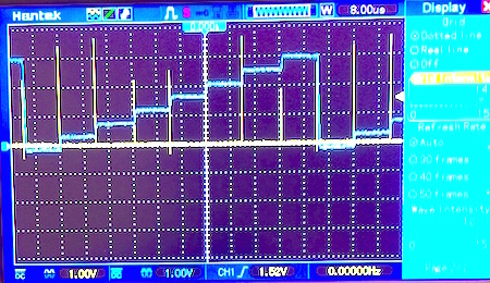
- With a wire jumper between the DAC0out pin and the A0/PTB2 pin of the FRDM-K64F, an oscilloscope trace of the DAC output shows the sawtooth waveform and the 12.5 microsecond timing, as seen below. The yellow spikes shown below in the second trace are the DO digital I/O, and show the sampling instants, since the digital I/O is toggled just before the DAC and ADC are triggered.
Signals at D0 pin (yellow trace) and DAC0out pin (blue trace).
FRDM-K64F FFT mbed code
For signal processing in the embedded processor of the FRDM-K64F
See the Mbed CMSIS DSP libraries for DSP functions (FFT, matrices, serial, etc.s
- Near line 166, is the FFT code, as shown below
- Time data is first copied into array fftDat, ifftFlag=0 sets forward-FFT, size is TEST_LENGTH_SAMPLES
- WARNING: FFT size must be a power of 2 from 16 to 4096
- Final result is stored in the oroginal array, fftDat (original contents of the array are lost!)
float32_t fftDat[TEST_LENGTH_SAMPLES*2];
for (int nn=0; nn<TEST_LENGTH_SAMPLES*2; nn++)
fftDat[nn]=timeDat[nn];
pc.printf("begin fft \r\n");
arm_status status = ARM_MATH_SUCCESS;
arm_cfft_radix2_instance_f32 S;
ifftFlag = 0; //forward (ifftFlag=0) or inverse (ifftFlag=1)
doBitReverse = 1; //Set=1 for output to be in normal order
fftSize = TEST_LENGTH_SAMPLES ;//WARNING: only choose power of 2 from 16 to 4096
status = arm_cfft_radix2_init_f32(&S, fftSize, ifftFlag, doBitReverse);
pc.printf("begin fft \r\n");
arm_cfft_radix2_f32(&S, fftDat);
pc.printf("end fft \r\n");
for (int nn=0; nn<TEST_LENGTH_SAMPLES; nn++)
pc.printf("fft dat=%u %f %f \r\n", nn,fftDat[2*nn],fftDat[2*nn+1]);
The following tutorial introduces Java/NetBeans tools for use in course projects. In the following, audio sound files are used as the source of signals that will be digitally processed. Similar data can be obtained using the ADC in the FRDM-K64F. The audio files have the added benefit of allowing the results of digital filtering operations to be heard. In addition, the graphic user interface provides display of the time and frequency domain for the signals. Finally, the user can easily add DSP functionality to buttons on the interface by editing/adding Java code, as outlined below.
However, please note that in this course the focus is on doing the signal processing in the embedded processor of the FRDM-K64F, as illustrated on the FFT example included in the mbed software file frdm_etherClient_netBeans_b_zip_k64f.zip . See the Mbed CMSIS DSP libraries for FRDM-K64F DSP functions such as FFT, matrices, serial, etc.The advantage of Java and NetBeans is that it is readily available and portable across many machines/platforms. The Java programming language is quite similar to C++, and C++ users will quickly adapt to Java. Notable differences are that Java does not support overloaded operators, and "this" in Java is equivalent to "*this" in C++.
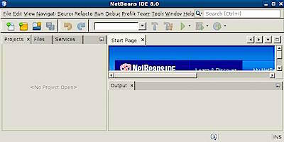
Start NetBeans
See installation of NetBeans above. When you first run NetBeans, you should see something similar to the window shown below. NetBeans has many different views and window panes. A typical layout of NetBeans is shown below.
Load the twDspNetBeansFrdmK64Fether_b-DSPsoundv55a GUI for the class
Open the twDspNetBeansFrdmK64Fether_b-DSPsoundv55a GUI (Graphical User Interface)
The twDspNetBeansFrdmK64Fether_b-DSPsoundv55aUI GUI shown below contains all of the buttons and graphical display areas that will be used in the course. Some of the buttons are functional, but you will need to add the remaining functionality throughout the projects in the course.
Saving Backup Copies of a Project
Now would be a good time to save a backup copy of your work. This is easily done in the ProjectPane. Make sure the ProjectsTab is selected so that the ProjectPane is visible in NetBeans. Then, right-click your top-level project (twDspNetBeansFrdmK64Fether_b) in the ProjectPane, and select CopyProject. The default name of the backup copy, twDspNetBeansFrdmK64Fether_b_1, should appear.
Building and Running a Project
At this point try to build the project
Adding Actions to Buttons (Event Handlers)
The window has many other buttons, but nothing happens when the other buttons are pressed (except for a printout at the bottom of the window). To make something happen, we need to add code to the event handlers.
For example, suppose we wish to change the message for the "A" key. To do this:
Using the Myclass Java Class
While simple functions may be directly coded in Java, it is often much easier to create a new Java class to encapsulate functions and data. Such a Java class enables quick re-use of common functions such as addition, multiplication, Fourier, convolution, etc.
In the DSPsoundv55a program, a Java class called "Myclass" is included. This class includes arrays of real and imaginary data, and provides functions for Fourier, addition, etc. To view the class, right-click the Myclass.java file in the ProjectPane and open the file. As shown below, the Myclass functions are listed in the NavigatorPane in the lower left. Click on the plus(int x) in the NavigatorPane to jump to the plus(int x) function in Myclass.java, as shown below.
In the source code above, plus(int x) uses a for-loop to add the integer value stored in variable x to all the elements in the array of real parts of the data, (this.re)[nn]. Notice that there is no return value (hence the declaration of "public void"), and the operation is done on the original copy of the data. Further, note that there is a different plus function defined for adding two Myclass arrays together, plus(Myclass x). Finally, note that there is an equals(Myclass x) function to implement "=" that would normally be implemented as operator= in C++. (Recall that Java does not support overloaded operators.)
Note, for the Ethernet FRDM-K64F project:
- Note also that there are two important Ethernet access functions for the FRDM-K64F in tpw.myClass (purple arrow above): k64fGetFreqData() and k64fGetTimeData(). These functions are called by jGetFreqButtonMouseClicked and jGetTimeButtonMouseClicked and jCloseServerButtonMouseClicked, implemening the "getTime" or "getFreq" buttons in the interface.
Data Structure of Myclass Java Class
The basic data structure of the "Myclass" Java class is declared at the top of Myclass.java:
From this, it can be seen that the class consists of an array of bytes called data[], two arrays of floating point called re[] and im[], and an integer n. In use, the integer n holds the size of the arrays, and arrays re[] and im[] hold the real and imaginary data, as "floats" (floating point arrays). (In Java, the array indices range from 0 to n-1.) Hence, a Myclass object can hold the sequence of sound samples in the real part of the array. For example, a 2048-sample sound clip could be stored in the array re[] from re[0] to re[2047]. Similarly, the complex values of a Fourier transform of the sound clip could be stored with the real parts in re[] and imaginary parts in im[]. The byte array is only used for internal use in reading audio files and playing sound, so do not use the byte array and assume that any operation such as addition, division, etc. is NOT performed on the byte array.
Constructors, Equals, and Functions of Myclass Java Class
As in C++, a constructor is used to create/instantiate a new instance of a Myclass object. For example:
Myclass a = new Myclass();
Myclass b = new Myclass(1024);
a.equals(b);
a.equals(b.fft());
a.plus(b);
In the above, the first statement creates a new Myclass object using the default constructor. The default constructor is defined by the function Myclass() in Myclass.java, and creates a default-sized array of size n=10. In the second statement above, the constructor used is Myclass(int nn), since the second invocation has an int argument, i.e., 1024. Therefore, the second constructor creates a Myclass object "b" with arrays of size 1024, and loads "n" with the value n=1024. Next, recall that Java methods (Java functions) are invoked by the syntax "object.method." So, on the left side of the period must be a Myclass object, and the right side must be a valid Myclass method. The statement "a.equals(b);" would set the contents of "a" equal to "b." The statement "a.equals(b.fft());" sets "a" equal to the FFT of "b." Note that the function fft() is a somewhat unique function that it returns a Myclass result on the stack, and can therefore be used as the argument of the equals() function. In addition, because the result is returned on the stack, you MUST use the equals operator to immediately fetch the result off the stack. This Myclass return value is evident in the declaration of the FFT function as "public Myclass fft()" whereas a declaration "public void whatever()" would return no value on the stack, and is the more typical behavior.
The final statement above, "a.plus(b)," would add the contents of b to the contents of "a" and place the result in "a." The following Java code is a simple implementation of a function "public void plus(Myclass x)" that would implement the above function to add two Myclass arrays together. In the example below, a for-loop adds the corresponding byte-data, real, and imaginary arrays. As in C++, the value of n in "xx < n" below would refer to "this.n", the value of n associated with the Myclass that invoked the function. More specifically, the value of n would correspond to "a.n" for the invocation "a.plus(b)". Also note that it would be better to add some code at the beginning of the function to check that the two arrays were the same size and that they were not null arrays (uninitialized).
In the code above, an extremely important concept is the keyword "this," where "this" is a handle/pointer that refers to the invoking object. The invoking object is the object to the left of the period, so "a: is the invoking object in the "a.plus(b)" example.
Another important feature in Java is the concept of overloaded methods, where the particular function/methofd that is invoked depends on the types of arguments used. For example, there can be another declaration of the "plus" method that adds an integer "c" to the Myclass variable "a" that would be called by writing the comand a.plus(c). In essence, the method "plus" is overloaded, meaning that it has different algorithms that may be called, depending on the types of variables involved. The new example of an integer "plus" command would be declared in the class perhaps as follows:
public void plus(int yy)
{
for (int xx = 0; xx < n; xx++)
{}
(this.re)[xx] = (this.re)[xx] + yy;
(this.im)[xx] = (this.im)[xx] + yy;
}
Example of the Power of Java Classes
A good example of the power of Java classes is the implementation of the 2lnFFT button. The code to implement taking the FFT and log-magnitude of a soundfile using the 2lnFFT button is essentially only two lines long:
Note the simplicity of the above code, and the readability of the code.
So, encapsulate all of your complex code into powerful functions in the Java class Myclass. This efficient use of your Java class will make the high-level code much easier to read and will make it easy to re-use your functions.
Data Storage in dispData, inData1, inData2 in DSPsoundv55aUI.java
Returning to the twDspNetBeansFrdmK64Fether_b GUI program DSPsoundv55aUI.java, three Myclass variables are used to store/access data. These variables are defined near the bottom of theDSPsoundv55aUI.java file, and are accessible to all of the functions in DSPsoundv55aUI.java. Variables inData1 and inData2 are used to store the contents of sound files read in by the "Read1" and "Read2" buttons. Variable dispData is used to hold the contents of the data displayed on-screen. Anything stored in dispData will be plotted on-screen at the next invocation of the refreshDisplay() function.
For example, consider the implementation of the "Read1" button in "private void Read1Clicked(...)." as illustrated below.
The first statement fetches the filename from the window text field and stores it in the global String variable inFileName1. The second statement uses the global Myclass variable inData1 to invoke the readau() function to read the file. This readau() function resizes the arrays in inData1 and stores the audio data in the real array re[] contained in inData1. Finally, the contents of inData1 are stored in dispData, so that the newly read sound file will be displayed after refreshDisplay() is called in the final statement. (Recall that the refreshdisplay() function always refreshes the display using the current contents of dispData.)
File Output in twDspNetBeansFrdmK64Fether_b DSPsoundv55aUI.javaMore Java Resources
As part of the function refreshDisplay() in DSPsoundv55aUI.java, three ASCII text files are written every time the display is refreshed. Files F1.txt and F2.txt are written with the contents of global variables inData1 and inData2 (typically the soundfile data read in by buttons "Read1" and "Read2."). File disp.txt is written with the contents of global variable dispData, the data currently displayed on-screen. These files allow the user to see the raw data associated with the plots on-screen.
In addition, the "Write png" button allows the user to save the current display as a ".png" image file for easy inclusion of data in project reports.
If learning Java, try not to become bogged down in details of window design, widgets, graphics, pop-ups, and so forth. NetBeans takes care of most of the user interface issues. Also, do not study applets, these are not required. Your time will be best spent of 1) what is a Java class, 2) for-loops, 3) arrays, 4) constructors, 5) variables.
java tutorials 1
java tutorials 2
java tutorials 3
NetBeans : http://www.netBeans.org/
Execution Problems when Running Outside NetBeans
Note: if the windows-click-and-run is installed incorrectly, you will need to open a command-prompt window and type "java -jar myjarfile.jar" to run myjarfile.jar. The jar files are most commonly in the "dist" subdirectories of NetBeans projects. Or, you may just run your application from within NetBeans.
Some Error Problems
On occasion, the project may not run on a machine that is running an older version of Java. You may get error messages such as "Unsupported major.minor version 49.0." You can check the version of Java on the machine with the "java -version" command. This tutorial used version 1.5 of Java. You may need to upgrade the version of Java on the machine to get your code to run properly.